HAPCO VANG AND JIB HALYARD SYSTEMS OVERVIEW
By Barney Harris 6701 & 8011
HAPCO has developed smooth running vang and jib halyard controls for the Albacore; both are the result of trial and error over the past several years of Albacore racing and rebuilding.
JIB HALYARD
Please forgive the “Patent-ease” her, but it’s the only way to really convey all the details with no chance of misinterpretation. The jib halyard 1 is a length of 1/8 inch 7×19 stainless wire rope. The top end is fitted with a captive pin shackle 2 and connects to the head of the jib 3. The hauling end is fitted with a 30 inch loop 4 that serves to keep the crimp fitting 5 always in the mast throughout its range in travel. This feature prevents the halyard 1 from hanging up in use and reduced fatigue near the crimp fitting 5, since it is never flexed.
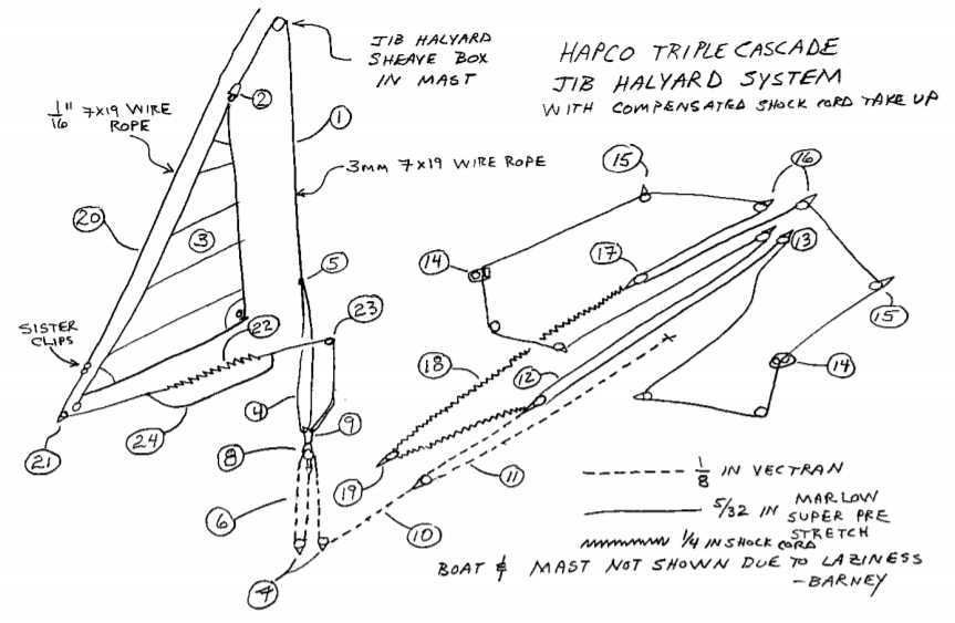
The jib halyard system uses a 3:1 tackle 6 at the mast. Two single hi load sheaves 7 are affixed adjacent to the mast step. A single hi load block with becket 8 with a captive pin snap shackle 9 connects to the jib halyard 1 where it exits the mast, just under the deck. The hauling part of the first stage 10 is lead aft along the centerboard trunk and connects to two cascaded 2:1 purchases 11 and 12. The final purchase is lead all the way to the transom 13, then forward to the side consoles where it ends in a cam cleat 14. The line lengths are adjusted such that the entire system remains aft of the centerboard pin when eased and just two blocks in the stern as the 3:1 cascade two blocks at the mast step. This gives a range of motion of about two feet, and enables both short and long luff jibs to be used without altering the boat. It also enables the jib halyard to be released enough to slacken the jib luff while the mast is back to the gate.
The second part of the jib halyard is the compensated take up system. This relies on a continuous loop of line. From the cleat the tail 14 is lead aft and to swivel blocks under the rail 15, and thence to the center of the transom 16. A bight of line where the two sides join is reeved through a bullet block 17 connected to a length of shock cord 18. The shock cord is lead forward, around a block 19 in front of the centerboard trunk and aft to the third cascade stage 12. This serves to compensate the take up – as line is payed out, the shock cord 18 is eased in exact proportion, so the take up always has the same preload. The compensated shock cord take up also serves to pull out the third stage 12 of the jib halyard cascade.
The forestay 20 is attached to the mast, lead through a turning block 21 at the stem, aft over the fore deck, connected to a short length of shock cord 22, and around a thru deck block 23 and down alongside the mast at the partners, and connected to the shackle 9 at the top of the jib halyard first stage 6. This system keeps the forestay 20 tensioned at any jib halyard setting, and provides a constant reference from which one can gauge luff sag while sailing to windward. In addition, the forestay shock cord 22 serves to pull the first and second stages 6 and 11 when the jib halyard is eased. An additional length of line 24 is run in parallel to the shock cord 22 to keep the mast from falling if the shock cord 22 were to fail – in accordance with rule 12.1.
The combination of forestay and take up shock cords 18 and 22 enable the crew or driver to ease the jib halyard in any conditions – even when the jib luff is slack. The small amount of friction in the cascades 6, 11, and 12 are overcome by shock cord 18 and 22 tension. As a consequence one never needs to stand up and yank on the shroud to drop the mast back when sailing down wind: simply ease the halyard at the control and the mast falls back under its own weight.
BOOM VANG
The vang system is also a triple cascade. Stages one and two are 2:1 each and with a 4:1 final stage produces a total purchase of 16:1. The vang tackle is dead ended at the mast 1 base 2 with a snap shackle 3. Stage one leads from the mast base to a Harken HK300 wire rope block 4 permanently mounted to the boom 5. The hauling part of the first stage is lead to a second HK300 6. The second stage is also dead ended at the mast base 2, lead through the second HK300 6 to a low load double block 7. 1/8 inch vectran line is used for the first two stages. The third stage passes through the double block 7 to a single block 8 at the mast base 2 and finally to two swivel blocks 9 and 10 mounted just aft of the mast step, where the hauling part is redirected aft along the centerboard trunk. Swivel blocks 11 and 12 under and thru deck blocks 13 and 14 in the thwart lead the hauling part to two cam cleats 15 and 16 on the side deck consoles. 5/32 inch marlow super pre stretch is used for the third stage.
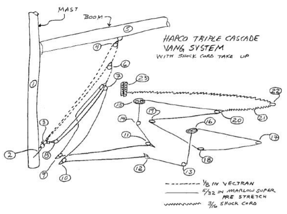
The tail is lead aft from the port cleat 16 to a cheek block 17 affixed under the rail on the port side, then forward to a cheek block 18 on the seat tank, and then across the boat over the centerboard trunk just aft of the thwart to another cheek block 19 which turns it aft on the starboard side to a floating bullet block 20 connected to a shock cord 21, and then to the other console cleat 15. The shock cord 21 is lead aft to a cheek block 22 mounted under the rail, and forward to the chain plate 23. For light air, the shock cord 21 is disconnected from the chain plate 23 to allow the vang to be eased totally slack.
While sailing,the vang is being adjusted nearly constantly in response to wind strength fluctuations. The 16:1 purchase is adequate, but not too much. The shock cord take up cleans up the tail after an adjustment. The vang is easily adjusted by either crew or driver. I will often have my crew sail with the vang in their hand and adjust the vang in real time as the breeze varies.
EFFICIENCY
I have measured the efficiency of several different tackle systems and have found that it is absolutely critical to have a system that uses the absolute minimum number of blocks and no sliding contact or foul leads anywhere. I have found that about ten percent of tension is lost for each time a line passes over a brand new top qua lity ball bearing sheave. This translates to an efficiency of 5% for each 2:1 purchase. I have also noted that in other boats that it is critical that every block be correctly aligned and to not chafe. I found the efficiency of the above described jib halyard system to be about 50 percent. This means that a tension applied by the crew will result in a jib halyard tension equal to the product of it and the efficiency. So, if the crew pulls the above described 12:1 jib halyard system with a force of 10 pounds, the resulting tensions will be 10lbs(12)(50%) or 60 pounds.
Frequently, people’s initial reaction to what seems like a mass of lines and blocks is that the system is “too complicated.” But consider this: racing dinghies is complicated. You must keep the boat balanced and going fast, adjusting to wind and sea conditions every moment all the while the issues of real importance are on the water half a mile away. The last thing you want to deal with is making sure your feet are not tangled in the tail end of the vang control when you must lay that perfect lee bow roll tack on someone. The advantage of these systems become apparent while racing – the ability to simply adjust the vang or jib halyard without having to hunt around for the control, without having to relocate the crew’s but, without having to worry about the tail getting fouled in the main or jib sheet block, and never have to think about running out of travel since they are continuous. This enables the helm and crew to keep their eye one what’s important – everything outside the boat.